Example of a Weight and Balance procedure
Usable on most aircrafts, shown here for the Mitchell B-10
Page last revised on July 30, 2003
Contents:
1 - Intro
2 - Example on the Mitchell B-10
3 - Weight and balance sheet of my B-10
4 - Additional info
1. - Intro:
Legal disclaimer:
This article explains the process and calculations that allow to locate
the center of gravity of a projected or existing aircraft.
This explanatory document was written solely on the basis of my current
knowledge of aircraft construction and can in no way be regarded as an accurate,
professional or approved document, unlike FAA publications.
For the B10 ultralight in particular, but also for the U2 superwing,
This procedure does NOT replace the procedures and data lined out by
Don Mitchell.
It is very useful for several purposes, though, like
estimating where an engine should be placed, how much a pilot's relocation forward or aft
inside the aircraft moves the CG, and how much the fuel consumption
in respect to the tank location changes the CG during flight, etc.
Objective of this document:
The weight and balance sheet for any aircraft is used solely to determine
wether the CG in flight is within the range that the designer allows for.
Under NO circumstances this procedure allows you to determine where to place the CG on
a new aircraft design, even less on a new or modified flying wing design.
CG placement on flying wings is a source of high-level discussions, and
even the best designers and aerodynamicists can only give you theoretical
data that need to be confirmed and/or adjusted during test flights.
Needless to say, in the homebuilder's world, RC model test flights on
not too far scaled-down models (1/2 or 1/3) are the way to go, and will save your
a.. and quite some bucks!
How did I come to use a Weight and Balance sheet on the B10?
Well, the french government requires a correctly filled-in weight and balance
form for registration, even for a homebuilt ultralight.
Not knowing what to do, I got the info on how to use the weight and balance procedure from
the equivalent of the EAA's journal, which is the RSA's journal in France.
Again :A WORD OF WARNING:
The calculation of the CG with the weight and balance sheet does NOT replace the CG check
on sawhorses like it is used on the B10. This method is still the most accurate and
safest - Don Mitchell knew that.
Still, the weight and balance sheet allows a quite exact determination of the
resulting CG during assembly of the trigear cage, for example.
The tolerance between calculation and reality that I found is about 1 inch, which is not bad at all.
If looking carefully at my diagrams you might notice that on my ship, the difference is 2 inches, but only
because my ship was built by Bernard Fournier with almost 13 degrees sweep instead of 12,
which puts the reference point given by Don Mitchell further aft than the actual flying CG.
Said in other words, 13 degrees sweep already gets you into prototype-land!
2. - EXAMPLE of the weight and balance procedure for a B10:
As on all aircrafts, a number of reference points need to be set along
a line on the longitudinal axis of the aircraft (axis in flight direction).
Just draw a chalk or pencil line on the floor and align your ship on it.
Put a block under the rear skid or stinger to get the front wheel touch the ground.
Block the wheels so that the ship wont move along the line.
Fig.1: B-10 with a number of stations (reference points) along its longitudinal axis.
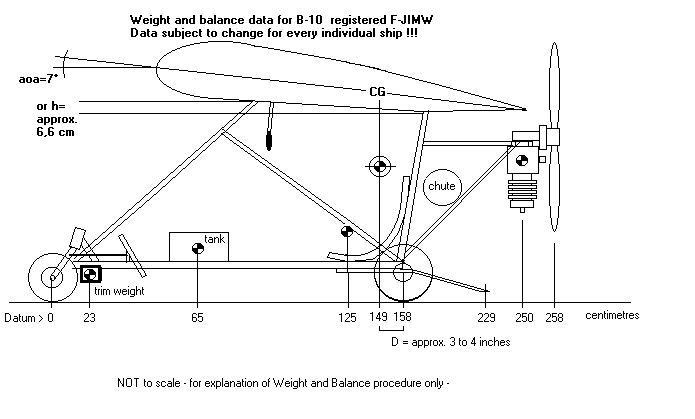
We start anywhere we like, (some planes have this reference point several feet
in front of the prop cone, others on the firewall, etc. In this case I
chose the front wheel axle (while the 3-view picture in the B10-plans
specifies the leading edge at rib 0, but that would need negative numbers
for all the locations forward from there, so I chose the front wheel
axle.) Use a weight on the front or a wood block under the stinger to get
the ship into a flying position, which is 7 degrees up for the wing chord
at rib 0).
With a large square, mark all important stations: place on the fork base, where I'll attach trim weights,
then the center (CG) of the tank (easy for a cube shaped container),radio attachment location,
recommended CG of the aircraft, with forward and aft limits.
Use a lead part or heavy nut and a string to plot these
locations down from the wing to the ground accurately.
The forward and aft CG range limits are given in the plans, while the actual flying CG
is on a line between two points at 4 inches inboard ribs 5 on the spar underside.
To plot this point down to your line, proceed as follows:
Tape a thin sewing thread to the two points under the spar and pul it just straight.
It will cross rib 0 at a point that should be between the two CG range limits.
Mark a dot under rib 0 at that point. Also mark the spots where the thread crosses the
Tubes that interconnect forward and aft hang fittings on the trigear cage.
From these tubes you can then transfer the CG location to the ground with a little weight on a string.
Continue with the Pilot's CG (sit in the seat and check where
you navel is (compared to the line, I mean ;)
- that is roughly where a normal homo sapiens's CG lies. (allow for a big head or lead boots, though ;)
Further aft, mark the mains gear axle point and the engine's CG (you may need to hang it
from the ceiling once, to find where it is, and weigh the engine at the same time.
If you do that with the prop on the engine,
write that down, otherwise mark the prop location further aft on the
line and eventually weigh the prop, too. This will later allow you to know the CG change
a heavier or lighter prop would cause, if any, in almost no time, using your balance sheet.
Now comes the actual weighing procedure:
If the pod / cage is partially complete or finished, set the ship up so that all three wheels
are on the ground, using a block under the stinger, but with just NO weight on the front wheel,
i.e. the front wheel about 1mm off the ground.
Get a weighscale used to weigh persons. Prefer a electronic model with max. 1lb
error. Get 2 blocks just as high as the weigh scale, plus the one needed to lift the stinger, which should have a known weight.
If you still are looking for the best weight distribution and you are in the process of
assembling the pod or cage, hang the engine and prop into the cage/pod at the location you want it to be in, add all hardware of which you know that it will be there: tubes for the engine mount, fuel pump, chute, everything.
Now weigh the weight on the right main gear wheel with the two blocks
under stinger and left main gear wheel.
Shift the weigh scale around until you have the three readings. the ones on the main wheels
should be close to each other within 1lb (of course).
Weigh the pilot in full flying apparel.
Note down all the figures and move on to section 3.
If you have a helper, you can of course weigh everything with the pilot in
place, but the the weight on the front wheel is then needed, while the stinger
should lift off the ground. If it doesnt, you already know there is
something to look at later (your flying CG is behind the gear axle dont laugh, it happened to
me at an early design stage of the trigear cage!).
rudders to it, and then lift it up on two sawhorses until you find the point on the spar where it is in balance. This will be at a different place from where the final flying CG is. With a string, plot the sawhorse location on rib 0 or the two adjacent ribs #1.
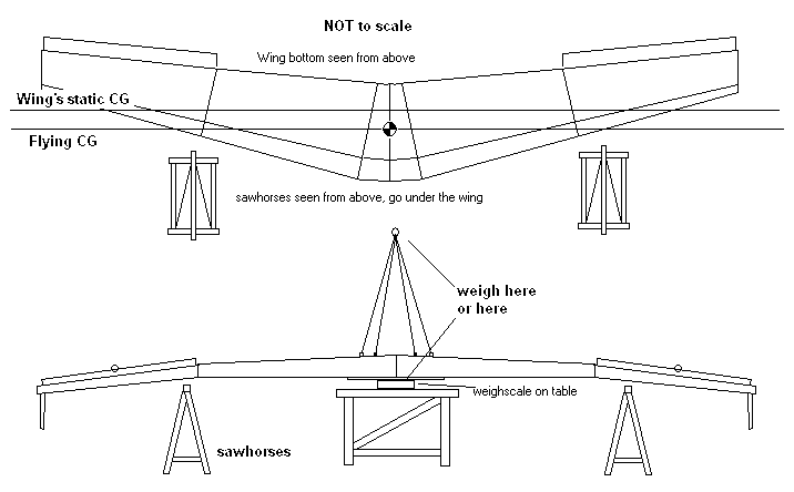
Lay the wing back on the table and carefully, hang it off the ceiling, using the hang points (use bolts, and dont allow the four ropes you need to pull too much fwd/aft on the fittings by making them as long as possible).
Use a fish scale of sufficient rating to weigh the wing.
Of course you can also lay the wing on a weigh scale if you have one with a display that can be read from the front or that is detachable. Use a plank with known weight to distribute the weight of the wing on ribs 0 and the 1s to avoid damage. For once, dont use thick foam for protection here, because the wide 1mm capping of the 0 and 1 ribs would crack.
3 - Weight and balance sheet of my B-10
Now comes finally the simple calculation sheet that does it all:
3.1. empty CG calculation
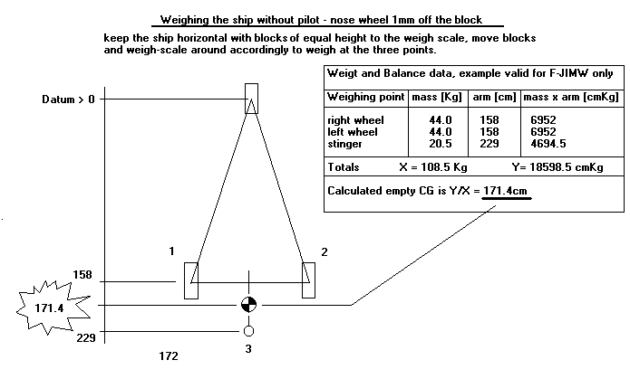
Just put your figures in the sheet. You'll see that in this sheet, only the
wheel / stinger positions are used, keep the other data (engine, tank location, etc. for later use.
My example uses centimetres and Kilograms, but it works as long as you use the same units throughout, inches and pounds, for example.
it's old greek science invented by Archimedes - you can trust it.
Your empty CG on a B10 typically is behind the mains gear, thats why
the ship noses up and "sits down" on the stinger as soon as you get out.
(if it does not, something may be wrong..)
3.2. flying CG calculation
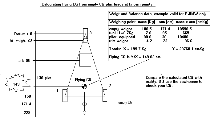
Except if you won this on the first go (I doubt it) you'll find out at least which way you'll have to shift the CG.
Now you will either have to play with lead on the nose (you can calculate how much it takes)
or shift the pilot forward (you'll see that it takes quite some pilot shift for a little CG
shift.
You might find that the engine weight is the main problem, and add the weight of the engine separately.
This way, the ideal position for the engine can be calculated, or you just "play" with the
pilot and engine positions until you get near the wanted CG position.
You can also solve the mass by moment equation the other way round to find the length of the
arm that you need to suspend a known weight so that the CG is where it should be.
Ill make an Excel sheet for this a.s.a.p., but feel free to do that for me ;)
Now last comes the CG range diagram with the in-flight CG travel due to the fuel consumption:
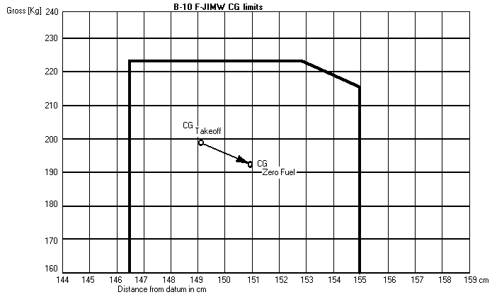
On the left side you set the weight axis, on the bottom the line with the reference arm in respect to the datum,
Now to get a diagram that not just contains a little spot in the middle, where the CG range is,
we have to "zoom in" (FAA people usually goof up when they see a flying wings CG "range" which rather like
a spot.)
Start the weight axis at a point where the weight equals empty weight plus a minimum pilot weight.
Choose the top of the weight axis just beyond the designed max gross weight (with your engine, because a 10HP engine would not get a B10 at max design gross weight anywhere near to the sky.)
Start the datum axis a few inches short of the most forward location allowed and a few inches beyond the aft CG limit.
Basically you can draw a rectangle from the fwd CG limit up to the max gross level, aft to the aft CG limit, and back down to the datum axis.
But in practice, many aircraft can't go to full gross weight at
max fwd or aft CG, depending on the tank location, that's why their balance diagrams have the forward or aft, upper weight range corner of that square cut off.
This is the range where the fuel consumption would drive the CG out of range.
Do the calculation for full and empty tank and plot the two datum/weight coordinates into the diagram.
Regardless of the fuel quantity available, the CG should stay within the limits.
It can be seen that a tank between the pilot's legs, near to, or against the seat, changes the
CG very little (about 3/4 of an inch), and that the wing will be a little more tail-heavy at the end of a flight than when taking off with full tank.
DO this calculation for several tank locations, and you will see that high fuel quantities, far off the CG can be a problem.
A last thing to remember: the pilot in such a light aircraft is a significant part of the total weight, and by simply leaning forward or backward, he influences the CG location.
Update:
Here is the picture from the Mitchell instructions showing the
actual CG test setup.
Note the sawhorse position under the main wing panel, at
two points 4 inches inboard the one but last rib of the center panel (Rib#5), right under
the spar cap.
Be careful not to push too much into the spar skin nor into the fabric.
To achieve this, small, relatively hard rubber pads on the sawhorses are best. Guess who is sitting in the ship?
